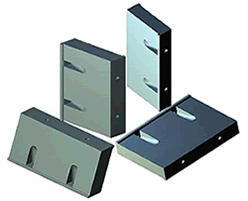
I Series Element Fenders
|
 Very high E/R ratio packed with excellent cost and space efficiency
Unrivaled installation versatility with its modular design
Fine-tune system performance with adjustable fender element length and
customizable grades
Work with other Zalda components such as structural PE front pad, steel
front panel with UHMW PE facing, mechanical mtion guidance device, and
various hardware to form different application system
Suitable for Zalda Technology Fender Monitoring System

|
 |
|
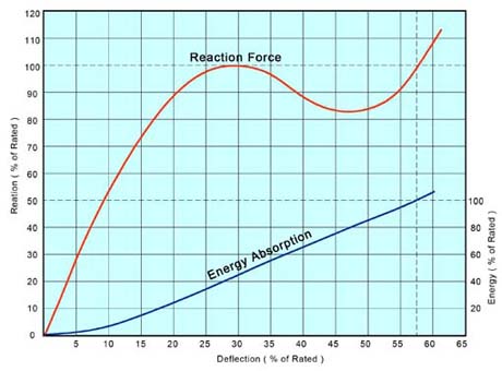
Performance
Information
|
|
- Typical performance curves shown here represent
general ER performance of the whole series. Actual performance of
individual model may vary slightly.
- Horizontal axis represent compression rate of
original fender height / standoff. Vertical axis represent energy
absorption / reaction force percentage of rated energy absorption (E) /
reaction force (R) values. See performance data table below for
rated ER value.
- E (energy absorption) in T-m; R (reaction
force) in T; All standard performance data listed has 10% tolerance
- Performance data listed for fender length of
1000mm. Calculate fender performance proportionally for fender at
diffferent lengths.
- Longitudinal / transversal angular contact
might result in significant performance reduction. Contact Zalda
for more details.
- Maximum fender deflection @ 62.5% yields 10%
more energy absorption / 20% more reaction force
- Only 5 of 30+ standard formula listed here in.
Customized performance model available with special rubber formulation
and critical section structure. Contact Zalda for more details.
|
 |
|
|
Model |
I |
I |
I |
I |
I |
I |
I |
I |
I |
I |
I |
I |
I |
I |
I |
I |
|
57.50% |
250 |
300 |
400 |
500 |
550 |
600 |
700 |
750 |
800 |
900 |
1000 |
1200 |
1250 |
1400 |
1450 |
1600 |
|
L1 |
E |
0.83
|
1.19
|
2.14
|
3.33
|
4.04
|
4.80
|
6.51
|
7.49
|
8.52
|
10.80
|
13.30
|
19.00
|
21.50
|
26.10
|
28.10
|
34.10
|
|
R |
8.06
|
9.69
|
11.50
|
14.50
|
16.00
|
17.50
|
20.30
|
21.80
|
23.30
|
26.10
|
29.00
|
34.70
|
37.60
|
40.60
|
43.50
|
46.40
|
|
L6 |
E |
1.05 |
1.45 |
2.62 |
4.07 |
4.77 |
5.86 |
7.76 |
9.16 |
10.4 |
12.9 |
15.9 |
22.3 |
24.7 |
31.9 |
33.6 |
41.7 |
|
R |
10.2 |
11.8 |
14.1 |
17.7 |
18.9 |
21.3 |
24.2 |
26.7 |
28.5 |
31.1 |
34.7 |
40.7 |
43.1 |
49.6 |
51.9 |
56.8 |
|
S1 |
E |
1.26 |
1.7 |
3.1 |
4.8 |
5.5 |
6.9 |
8.98 |
10.8 |
12.3 |
14.9 |
18.5 |
25.6 |
27.8 |
37.7 |
39 |
49.3 |
|
R |
12.3 |
13.9 |
16.7 |
20.9 |
21.8 |
25.1 |
28 |
31.5 |
33.6 |
36 |
40.3 |
46.7 |
48.5 |
58.6 |
60.2 |
67.1 |
|
S6 |
E |
1.47 |
2 |
3.56 |
5.56 |
6.57 |
7.99 |
10.6 |
12.4 |
14.1 |
17.6 |
21.8 |
30.7 |
33.6 |
43.8 |
45.7 |
56.8 |
|
R |
14.5 |
16.1 |
19.3 |
24.1 |
26.4 |
28.9 |
33.2 |
36.3 |
38.6 |
42.6 |
47.4 |
56.1 |
58.3 |
66.5 |
69.6 |
77.2 |
|
H1 |
E |
1.68 |
2.3 |
4 |
6.3 |
7.7 |
9.1 |
12.2 |
14 |
16 |
20.3 |
25.1 |
35.8 |
39.3 |
50.2 |
52.6 |
64.2 |
|
R |
16.6 |
18.3 |
21.8 |
27.2 |
31 |
32.7 |
38.3 |
41.1 |
43.6 |
49.1 |
54.5 |
65.5 |
68 |
74.3 |
79 |
87.2 |
|
|
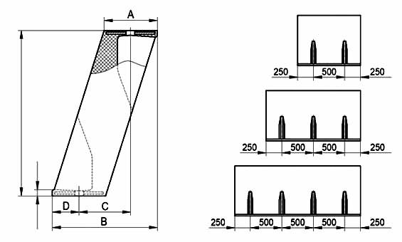
I Series Dimension Table
|
|
|
Model |
H |
A |
B |
C |
D |
E |
Bolt Size |
|
I 250 |
250 |
79 |
157 |
81 |
38 |
20 |
M20 |
|
I 300 |
300 |
95 |
188 |
98 |
45 |
20 |
M20 |
|
I 400 |
400 |
126 |
250 |
126 |
62 |
20 |
M24 |
|
I 500 |
500 |
160 |
314 |
144 |
84 |
20 |
M30 |
|
I 550 |
550 |
174 |
344 |
170 |
87 |
25 |
M30 |
|
I 600 |
600 |
188 |
372 |
200 |
86 |
25 |
M30 |
|
I 700 |
700 |
220 |
437 |
222 |
107 |
30 |
M36 |
|
I 750 |
750 |
236 |
468 |
238 |
115 |
30 |
M36 |
|
I 800 |
800 |
252 |
500 |
244 |
128 |
30 |
M36 |
|
I 900 |
900 |
285 |
565 |
274 |
145 |
35 |
M42 |
|
I 1000 |
1000 |
325 |
635 |
315 |
160 |
35 |
M42 |
|
I 1200 |
1200 |
385 |
760 |
372 |
194 |
40 |
M48 |
|
I 1250 |
1250 |
400 |
784 |
390 |
196 |
40 |
M48 |
|
I 1400 |
1400 |
440 |
875 |
445 |
210 |
45 |
M48 |
|
I 1450 |
1450 |
445 |
894 |
460 |
217 |
45 |
M48 |
|
I 1600 |
1600 |
500 |
995 |
485 |
255 |
55 |
M56 |
- All dimensions in mm.
- Standard fender length 1000 mm - 2000 mm. Custom length available on request.
- Bolt hole positions can be customized
- Allow inside buckling space of 0.6H and outside
buckling space of 0.25H in system design
|
|