Fender Systems | Quick Release Hook Systems | Mooring Bollards | Drives & Automation | Marine Monitoring & Control ¡¡


A Series Super Arch Fenders


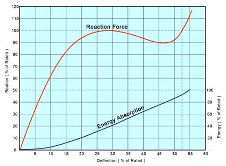
  Classic sturdy design with high E/R performance

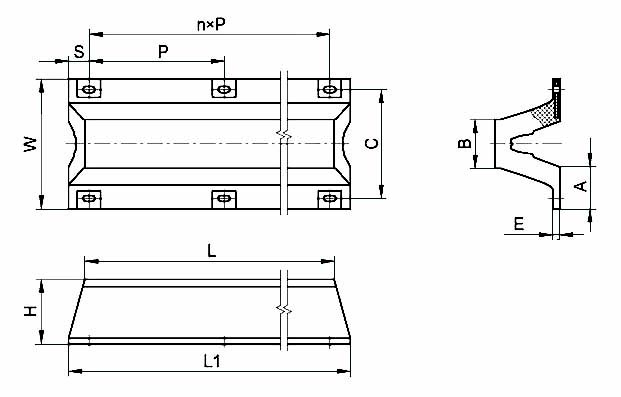
  Easy installation, maintenance and replacement

  Horizontal, vertical and diagonal installation schemes

  Suitable for small to medium size vessel

  Choices of contact surface including rubber, non marking rubber, PE pads, and steel structure backed PE pads, to suit different application requirements


supercell2.jpg (47239 bytes)


Performance Information


  • Typical performance curves shown here represent general ER performance of the whole series.  Actual performance of individual model may vary slightly. 
  • Horizontal axis represent compression rate of original fender height / standoff.  Vertical axis represent energy absorption / reaction force percentage of rated energy absorption (E) / reaction force (R) values.  See performance data table below for rated ER value.
  • E (energy absorption) in T-m; R (reaction force) in T; All standard performance data listed has 10% tolerance
  • Performance data listed for fender length of 1000mm.  Calculate fender performance proportionally for fender at diffferent lengths.
  • Maximum fender deflection @ 55% yields 5% more energy absorption / 10% more reaction force
  • Only 9 of 30+ standard formula listed here in.  Customized performance model available with special rubber formulation and critical section structure.  Contact Zalda for more details.
A Performance

Model A A A A A A A A A
52.50% 150 200 250 300 400 500 600 800 1000
L0 E 0.44 0.78 1.22 1.88 3.41 5.3 7.6 13.6 21.2
R 7.55 10.1 12.5 15.1 20.1 25.2 30.2 40.2 50.3
L6 E 0.53 0.95 1.71 2.47 4.52 7.04 10.1 18.1 28.3
R 9.19 12.3 16.9 20 26.9 33.6 40.2 53.7 67.3
S1 E 0.55 0.98 1.88 2.5 4.6 7.2 10.4 18.5 28.9
R 9.48 12.7 17.7 20.5 27.6 34.4 41.2 55 68.9
S6 E 0.63 1.13 2.24 2.98 5.4 8.49 12.2 21.7 33.9
R 10.9 14.6 21 24.2 32.3 40.3 48.4 64.5 80.7
H1 E 0.65 1.16 2.31 3.1 5.6 8.8 12.6 22.3 34.9
R 11.2 15 21.6 24.9 33.2 41.5 49.8 66.4 83
H6 E 0.74 1.31 2.69 3.92 7.01 10.9 15.7 27.9 43.6
R 12.7 16.9 24.9 31.2 41.5 51.9 62.2 83.1 103.8
SH1 E 0.76 1.34 2.87 4.1 7.3 11.3 16.3 29 45.4
R 13 17.3 26.6 32.4 43.2 54 64.7 86.4 108


A Series Dimension Table

A Dimensions

Model Dimensions
H  L L1 P n S B C W E A Bolt 
A150x1000 150 1000 1070 850 1 110 94 240 300 30 96 M22
A150x1500 150 1500 1570 670 2 115
A150x2000 150 2000 2070 620 3 105
A150x2500 150 2500 2570 780 3 115
A150x3000 150 3000 3070 710 4 115
A150x3500 150 3500 3570 670 5 110
A200x1000 200 1000 1100 860 1 120 125 320 400 35 128 M24
A200x1500 200 1500 1600 680 2 120
A200x2000 200 2000 2100 620 3 120
A200x2500 200 2500 2600 785 3 122.5
A200x3000 200 3000 3100 715 4 120
A200x3500 200 3500 3600 672 5 120
A250x1000 250 1000 1125 870 1 127.5 164 410 500 37.5 160 M27
A250x1500 250 1500 1625 680 2 132.5
A250x2000 250 2000 2125 620 3 132.5
A250x2500 250 2500 2625 790 3 127.5
A250x3000 250 3000 3125 715 4 132.5
A250x3500 250 3500 3625 673 5 130
A300x1000 300 1000 1150 870 1 140 225 490 600 33 195 M30
A300x1500 300 1500 1650 685 2 140
A300x2000 300 2000 2150 625 3 137.5
A300x2500 300 2500 2650 790 3 140
A300x3000 300 3000 3150 715 4 145
A300x3500 300 3500 3650 674 5 140
A400x1000 400 1000 1200 900 1 150 300 670 800 40 260 M36
A400x1500 400 1500 1700 700 2 150
A400x2000 400 2000 2200 635 3 147.5
A400x2500 400 2500 2700 800 3 150
A400x3000 400 3000 3200 725 4 150
A400x3500 400 3500 3700 680 5 150
A500x1000 500 1000 1250 930 1 160 375 840 1000 45 325 M42
A500x1500 500 1500 1750 715 2 160
A500x2000 500 2000 2250 645 3 157.5
A500x2500 500 2500 2750 810 3 160
A500x3000 500 3000 3250 730 4 165
A500x3500 500 3500 3750 686 5 160
A600x1000 600 1000 1300 960 1 170 450 1010 1200 54 390 M48
A600x1500 600 1500 1800 730 2 170
A600x2000 600 2000 2300 655 3 167.5
A600x2500 600 2500 2800 820 3 170
A600x3000 600 3000 3300 740 4 170
A600x3500 600 3500 3800 692 5 170
A800x1000 800 1000 1400 1040 1 180 600 1340 1600 72 520 M64
A800x1500 800 1500 1900 770 2 180
A800x2000 800 2000 2400 680 3 180
A800x2500 800 2500 2900 845 3 182.5
A800x3000 800 3000 3400 760 4 180
A1000x1000 1000 1000 1500 1100 1 200 750 1680 2000 90 650 M64
A1000x1500 1000 1500 2000 800 2 200
A1000x2000 1000 2000 2500 700 3 200

  • All dimensions in mm
  • Bolt hole positions can be customized
  • Standard fender length 1000mm - 3500mm.  Custom length available
  • Allow buckling space of 1W in system design


  All materials herein are properties of Zalda Technology, all rights reserved.
Site Designed & Maintained By Extranote Production for IE4.0 or Higher at 1024x768