|
|
||||||||||||||||
|
||||||||||||||||
Smart Fender SystemA Marine Fender Revolution
|
|
Link
to Smart Fender
PDF Literature
Link to
Technical Q&A ( Compiled, translated into english and updated
periodically. )
|
|
|
|
|
|
Smart Fender System, is a new cost realistic fender movement monitoring technology, that revolutionizes harbor fendering with sensor based / software aided Fender Design Weakness & Imminent Fender Failure Warnings, real time Berthing Accident & Fender Damage Alarms, and berthing impact statistical utilities. The many new capabilities made possible by the invention of the Smart Fender System will promote better berthing & fendering practices, and elevate harbor safety & maintenance standards. The Smart Fender technology was developed by Zalda Technology from aviation inertial guidance technologies, through close collaborations between the world’s top marine monitoring experts and marine fender specialists. |
CONTENTS |
|
|
Function Highlights
|
|
|
Real Time Accident & Damage Alarms Functions |
|
|
|
Fender Damage Alarms By monitoring fender movement range and static recovery posture, Smart Fender System can detect fender system permanent deformation, fender panel permanent deformation, and fender restraining device damages |
|
|
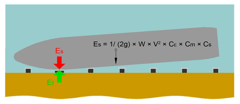
Ship Berthing Contact Speed & Energy Amplitude Alarms
Smart Fender System monitors ship berthing contact speed, calculates ship berthing energy amplitude, and generates alarms when berthing energy amplitude exceeds fender system design capacity |
|
|
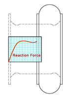
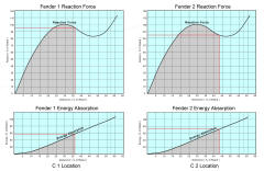
Ship Berthing Impact Load Alarms Smart Fender System monitors the Combined Instantaneous Reaction Load of all fender elastomers on the pier and generates alarms when it exceeds preset pier structural limit |
|
|
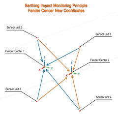
3D Fender Excessive Movement Alarms Smart Fender System monitors fender 3D movements and generate alarms when excessive displacement ( such as fender over compression ), speed ( such as berthing speed ) or angle ( such as berthing angle ) is detected. |
|
Advance Fender Design & Maintenance Warning Functions |
|
|
|
Insufficient Fender Design Warnings Smart Fender System automatically detects most common fender system design weaknesses. This allow Preemptive Fender Design Optimization be performed to avoid fender permanent damages and consequential damages on ship and dock structures. |
|
|
Imminent Fender Failure Warnings By following long term fender deterioration trends, Smart Fender System can predict imminent fender failures due to natural deterioration, which allows Preemptive Fender Maintenance be performed to minimize adverse influences of emergency fender maintenance. |
|
Fender Statistical
Design Optimization & Investigation Utilities
|
|
|
|
Historical Berthing Impact Distribution Graph Visualization of berth historical ship impact statistics allows easy optimization of berth fender system design, through fender asset reconfiguration and redistribution according to the actual demands of the application. |
|
|
Historical Data Replay The recorded historical fender movement / berthing impact data can be replayed on demand on the Smart Fender System GUI, for fender design optimization or accident / damage investigation purposes. |
| -- Contents -- | |
|
|
||||||||||||||||||||||||||||||||||||||||||||||||||||
|
|
||||||||||||||||||||||||||||||||||||||||||||||||||||
|
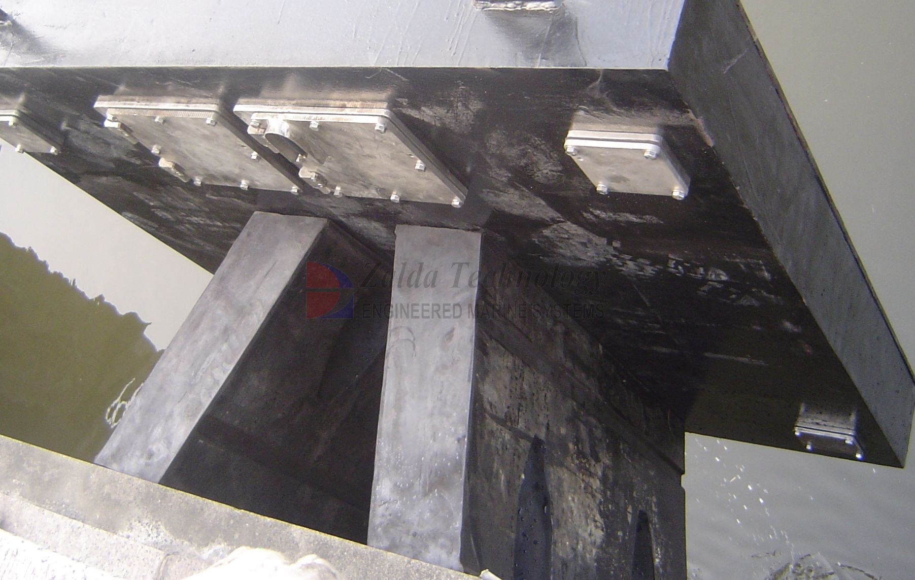
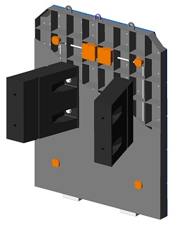
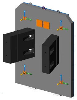
Waterfront components to be
installed on EACH fender system:
|
||||||||||||||||||||||||||||||||||||||||||||||||||||
|
Onshore / control room components
|
||||||||||||||||||||||||||||||||||||||||||||||||||||
|
* Additional components, such as audio - visual alarm, navigational aide and network extension devices, are also integrated as needed. |
||||||||||||||||||||||||||||||||||||||||||||||||||||
| -- Contents -- | ||||||||||||||||||||||||||||||||||||||||||||||||||||
|
General
Principles |
||||||||||||||||||||||||||||||||||||||||||||||||||||
|
      |
|||||||||||||||||||||||||||||||||||||||||||||||||||
| -- Contents -- | ||||||||||||||||||||||||||||||||||||||||||||||||||||
|
Better Fendering At Lower Costs
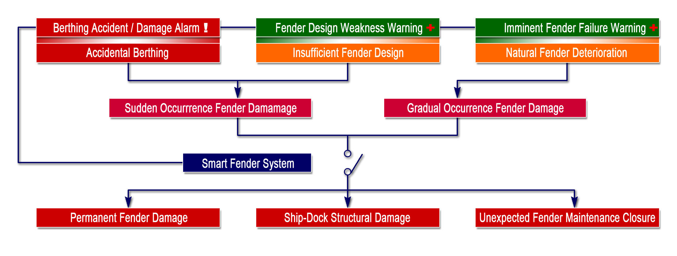
Smart Fender System seeks to address the sources of fendering and related costs, which can be classified into two categories:
n Sudden Occurrence Costs, Resulting From Berthing Accidents Or Fender Insufficient Design.
To address berthing accidents, Smart Fender System provides instant Berthing Accident / Fender Damage Alarms, along with relevant location and reading details. This helps port operators and emergency response personnel to promptly make informed decisions that could minimize the damages from the accidents. Then, Smart Fender System allow the causes of the accidents / damages to be identified through scientific means, using its permanent database and analytic tools such as Historical Data Replay and Berthing Impact Distribution Graph. These features enables engineers to accurately design counter measures that prevents the recurrence of accidents / damages.
Fender system design deficiency in most cases do not inflict immediately and apparent damages after fender initial installation, but bound to be very costly over time. The Fender Design Weakness Warning function of the Smart Fender System was designed to automatically discover and analyze the causes of the design deficiency, soon after fender systems are placed into service, giving us a second chance to avoid potential damages from fender design deficiency. This allows fender designers to perform necessary Preemptive Fender Design Optimization that prevents permanent fender damages and other consequential damages on dock and ship structures.
n Gradual Occurrence Costs, Resulting From Fender Natural Deterioration
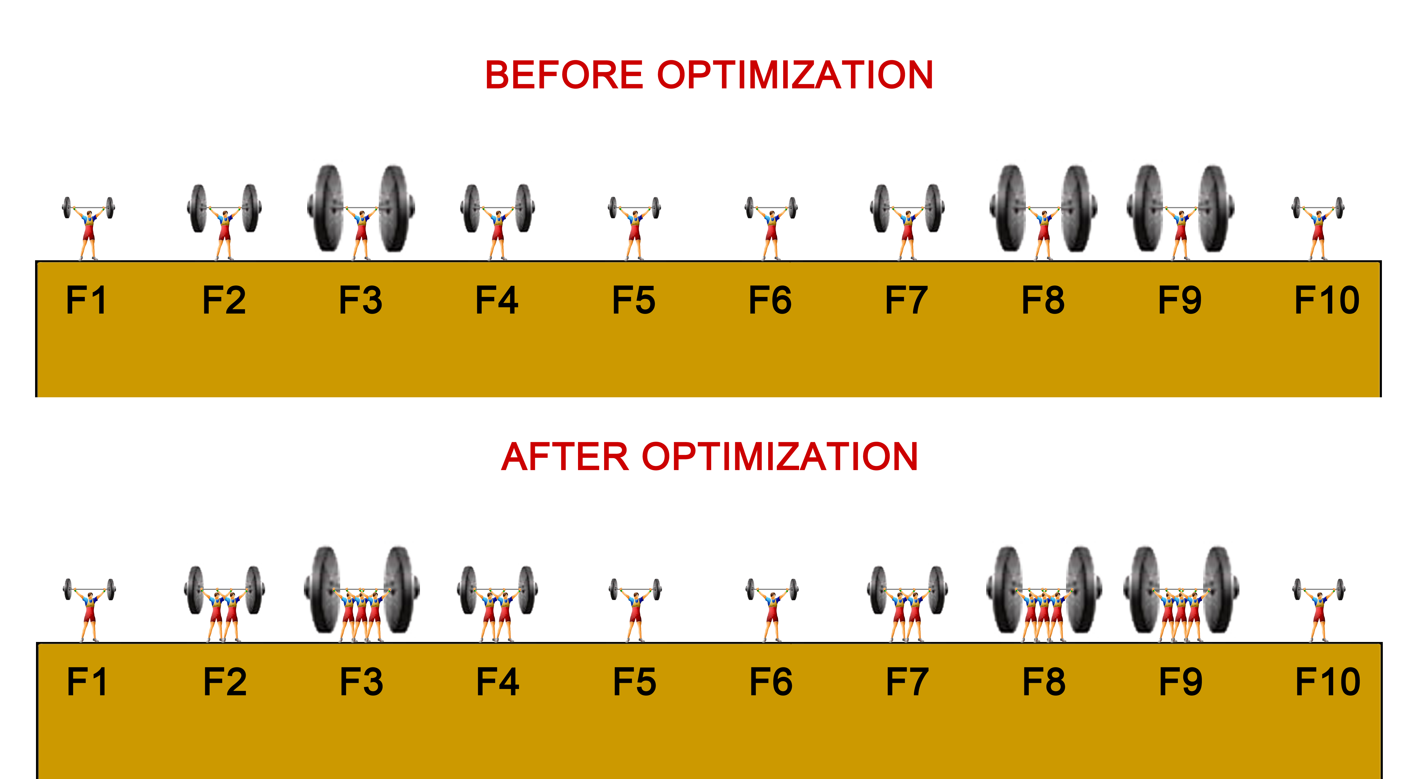
2/2 Impact Damand Based Fender System Design Optimization
Worldwide, it has been a standard fender design practice, to design individual fender system based on worst case berthing impact scenario, and then evenly distribute the resultant design across the entire berth. But in reality, berthing impact distribution on most berths is drastically uneven. This creates serious waste in fendering materials on a world scale. Smart Fender System allows historical berthing impact distribution on the berth to be visualized with its historical Impact Distribution Graph ( IDG ) function, which can be used to determine the adequacy of each fender system, and the necessity of individual components on each fender system. With IDG, fender designers can optimize berth fender system design per actual demand of historic berthing impacts, through reinforcing the usually small high impact intensity areas on the berth with higher fender configuration / density, while protecting the larger low impact intensity areas with reduced fender configuration / density. This creates a high probability to achieve far better fendering at much lower costs, especially for larger berths over a long period of time.
|
||||||||||||||||||||||||||||||||||||||||||||||||||||
|
|
||||||||||||||||||||||||||||||||||||||||||||||||||||
| -- Contents -- | ||||||||||||||||||||||||||||||||||||||||||||||||||||
|
Smart Fender Technology Background Information
Smart Fender System is a part of the motion tracking based Berthing Impact Monitoring technology ( BIM ) developed by Zalda. The main objective of BIM technology is to study the long term effects of ship berthing impacts on harbor structures. Other facets of BIM technology, such as pile motion - impact monitoring, fender based ship accidental drifting monitoring, and marine structure ( fatigue / seismic ) movement monitoring are also closely related to the development of Smart Fender System. The Smart Fender System is one of the 20+ applications developed on Zalda’s MMCS network monitoring – automation platform in the last 15 years. It is supported by MMCS multiplex information systems and integrates seamlessly with other MMCS applications, such as BSM berthing status monitoring, MLM mooring load monitoring, MEM marine environment monitoring and ACM mooring line release automation systems. Due to its strategic waterfront location, Smart Fender System could provide many elements of tomorrow's Smart Harbor Infrastructure outside the realm of fendering, such as shore power, hydrological monitoring, network infrastructure and navigational aids. Today's Smart Fender System is tomorrow's Smart Waterfront System in its infancy.
|
||||||||||||||||||||||||||||||||||||||||||||||||||||
 |
||||||||||||||||||||||||||||||||||||||||||||||||||||
| -- Contents -- | ||||||||||||||||||||||||||||||||||||||||||||||||||||
|
n
Battery replacement interval is dependent on choices of battery size and
quantity
n
Wireless communication range is dependent on transmission output
n
All specs are subject to revision without notice.
Please contact us to verify prior to ordering. |
||||||||||||||||||||||||||||||||||||||||||||||||||||
| -- Contents -- | ||||||||||||||||||||||||||||||||||||||||||||||||||||
|
|
||||||||||||||||||||||||||||||||||||||||||||||||||||
| All
materials herein are properties of Zalda Technology, all rights reserved.
Site Designed & Maintained By Extranote Production for IE4.0 or Higher at 1024x768 |